|
|
|
Who's Online
There currently are 6008 guests and
2 members online. |
|
Categories
|
|
Information
|
|
Featured Product
|
|
|
 |
|
|
There are currently no product reviews.
 ;
Even if the PDF is a scan, I can read the information I need.
The price is affordable and the service (mail sending) is very fast.
Thanks ! Regards. William (Fan of Kenwood)
;
Very good quality original datasheet!I like this amazing website!!!!!!
 ;
Excellent just what I needed to replace the electrolytic caps and make this old gem a beauty again. Was as scan of the original photocopied service manual.
;
It was helpful to get schematic with waveforms in important points and lot of service information. Manual is good quality, fast delivered. Of course it is hardcopy of paper one with all its disadvantages.
;
I want to give you a real heads-up for your desire to enable such people as I to acquire the information I need to maintain the older types of equipment such as this Akai HXA351W. You do a swell job with all the processes you have to perform so I can have a legible, thus usable
document which does not send me crazy trying to figure out the blurry text of a bad copy.
Very well done, Thomas.
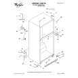
CHAPTER 4 DISASSEMBLY/ASSEMBLY
5.6.2 Replacing the Motherboard
This section includes the procedures required to replace the ColorPASS motherboard. Spare motherboards ship without memory, CPU, and the BIOS chip. The memory, CPU and BIOS chip from the old board will need to be installed on the replacement motherboard. a. To Replace the Motherboard 1. If you replaced the motherboard with a new board, replace the following components on the board: � Memory (see page 4-30) � CPU (see page 4-32) � BIOS chip (see page 4-34) 2. Angle the motherboard so the back panel connectors on the motherboard fit into the cutouts in the back of the tray. See F04-506-02 on page 4-27. 3. Align the mounting holes on the edge of the motherboard (opposite the back panel connectors) with the standoffs located in the base of the tray (see F04-506-02 on page 427). 4. Once the mounting holes in the motherboard are aligned over the standoffs, gently push the motherboard down to secure it to the tray. 5. Insert the 9 motherboard mounting screws to attach the motherboard to the tray but do not tighten them completely (see F04-506-01 on page 4-25 for screw locations). 6. Tighten the 9 motherboard mounting screws. Do not overtighten the screws; doing so could damage traces on the motherboard. b. To Replace Boards 1. Replace the following boards in the appropriate motherboard connectors: � UIB board in the connector labeled PCI1 � Display video board in the connector labeled AGP � Video board in the connector labeled PCI5 As you plug the board into the connector on the motherboard, make sure that the board connector is properly aligned with the connector on the motherboard. 2. Replace any option boards installed in remaining connectors on the motherboard.
4-28
COPYRIGHT© 2000 CANON INC. 2000 2000 2000 2000ColorPASS-Z90/60 REV.0 MAR. 2000
|
|
|
> |
|