|
|
|
Who's Online
There currently are 5882 guests online. |
|
Categories
|
|
Information
|
|
Featured Product
|
|
|
 |
|
|
There are currently no product reviews.
 ;
Complete service and operation manual. All schematics are there, all circuit boards AND add-on boards. Including exploded views ,component names and specifications. Also electrical and mechanical adjustment procedures are in this manual. This manual also covers the more advanced BR-S811E unit. Scan quality is fair and usable.
 ;
High quality scan of original Service Manual. Everything´s fine!
;
Good scan of the original service manual. All schematics and adjustment procedures are there. It helped me to fix a long lasting problem with the tracking circuitry. The manual also includes the supplementals 1,2 and 3. Included are; electrical schematic's , pcb layout's, mechanical drawing's and exploded views, disassembly manual and maintenance procedures. 236 pages.
;
The Service Manual received was helpful. The electronic information is exactly what I needed.
I recomend all of my friends about this technical page.
;
High quality scan of service manual. I am satisfied!
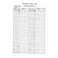
CHAPTER 5 TROUBLESHOOTING
Points to Note When Taking Measurements 1. Be sure that the three separation belts are in contact with the test strip. 2. Be sure that the test strip is pulled straight along the separation belt (Figure 5-131). 3. Be sure that measurements are taken when the rear end of the test strip and the rear end of the original tray are flush (Figure 5-136).
Upper cover Test strip Spring
Glued in place
[1] [2]
Glued in place
(rear)
Figure 5-137
Test strip 64 g/m2 80 g/m2 Feeding power (g) 520±20 570±20
(front)
Match the end of the test strip and the end of the original tray.
Table 5-109 Feeding Power
Spring gauge:capable of measuring about 600g (Tool No.CK-0058)
Figure 5-136 Measuring the Feeding Power (front) 7) Open the upper cover of the DADF to end measurement. 8) Loosen the lock nut 1 used to keep the front, and turn the adjusting screw 2 until the feeding power is as indicated. Then, tighten the lock nut 1.
Note: As a guide, try to limit the difference in feeding power between front and rear.
Direction of rotation Clockwise Counterclockwise Feeding power Decreases Increases
Table 5-110 Adjusting Screw and Feeding Power 9) Likewise, adjust the feeding power at the rear. 10) Measure the feeding power at front and rear once again. If the measurements are as indicated, firmly tighten the lock nut and glue it in place. Otherwise, make adjustments once again.
5-14
COPYRIGHT © 1998 CANON INC.
CANON DADF-A1 REV.0 DEC. 1998 PRINTED IN JAPAN (IMPRIME AU JAPON)
 $4.99 DADF-A1 CANON
Parts Catalog Parts Catalog only. It's available in PDF format. Useful, if Your equipment is broken and You need t…
|
|
|
> |
|