|
|
|
Who's Online
There currently are 5794 guests online. |
|
Categories
|
|
Information
|
|
Featured Product
|
|
|
 |
|
|
There are currently no product reviews.
 ;
A great copy of the manual, and the only one I could find anywhere on the net! The circuit diagrams are easily readable, all component values marked and easy to see. A highly appreciated download!
 ;
Great Manual. This manual is available no where else. It was exactly what I was looking for.
;
The TEAC A-1500's Service Manual was instrumental in reviving this classic reel-to-reel. Not only does it have the schematics, exploded parts diagram and parts list, it also provided mechanical adjustment information that approximate factory default settings.
;
This service manual was determinant to enable to fix my Alpine Amplifier. I am pleased with my purchase. For a 5 star rating I would like to see a higher resolution scan of the printed circuit board lay-out because the gray scale grafics was dificult to see. Also some schematic diagrams were scanned at a slight angle. Never the less, it had all information I needed to troubleshoot and service my equipment.
;
Complete manual, the good quality of reproduction allows enlarged print-out of the schematic diagram in the size it probably had in the original print edition and which is necessary for practical use.
CHAPTER 4 DISASSEMBLY/ASSEMBLY
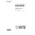
5.6.2 Replacing the Motherboard
This section includes the procedures required to replace the ColorPASS motherboard. Spare motherboards ship without memory, CPU, and the BIOS chip. The memory, CPU and BIOS chip from the old board will need to be installed on the replacement motherboard. a. To Replace the Motherboard 1. If you replaced the motherboard with a new board, replace the following components on the board: � Memory (see page 4-30) � CPU (see page 4-32) � BIOS chip (see page 4-34) 2. Angle the motherboard so the back panel connectors on the motherboard fit into the cutouts in the back of the tray. See F04-506-02 on page 4-27. 3. Align the mounting holes on the edge of the motherboard (opposite the back panel connectors) with the standoffs located in the base of the tray (see F04-506-02 on page 427). 4. Once the mounting holes in the motherboard are aligned over the standoffs, gently push the motherboard down to secure it to the tray. 5. Insert the 9 motherboard mounting screws to attach the motherboard to the tray but do not tighten them completely (see F04-506-01 on page 4-25 for screw locations). 6. Tighten the 9 motherboard mounting screws. Do not overtighten the screws; doing so could damage traces on the motherboard. b. To Replace Boards 1. Replace the following boards in the appropriate motherboard connectors: � UIB board in the connector labeled PCI1 � Display video board in the connector labeled AGP � Video board in the connector labeled PCI5 As you plug the board into the connector on the motherboard, make sure that the board connector is properly aligned with the connector on the motherboard. 2. Replace any option boards installed in remaining connectors on the motherboard.
4-28
COPYRIGHT© 2000 CANON INC. 2000 2000 2000 2000ColorPASS-Z90/60 REV.0 MAR. 2000
|
|
|
> |
|